Design for Manufacturing: Design for Assembly
Design for Assembly incorporates several significant tools to achieve a more cost-effective product. Engineers must determine if a product should be assembled manually, with automatic assistance, or entirely by automated processes. Engineers must also design the product in such a way as to minimize handling and insertion times. Finally, engineers must ensure that the product can be assembled with minimal chance of errors. While balancing this, engineers must still produce a cost-effective product that meets all tolerances and design constraints. Because of these requirements, Design for Assembly is a critical tool in the product development lifecycle.
As the assembly phase costs may outweigh overall manufacturing costs in some industries [1], it is critical to minimize assembly costs. Product assembly times may be calculated using the Boothroyd-Dewhurst handling and insertion time calculation method. Using precisely calculated tables, an engineer may use geometric manipulation combined with the force required to produce a rough approximation of the assembly time. Redesign may be a viable option for parts that show excessive assembly time. If a redesign is performed, the engineer may repeat the time study to determine if the expected savings of the design change exceed the cost of performing the retooling required to make the product change.
Parts should generally be designed to minimize the opportunity for nesting or tangling. Nesting describes a part that has become captured by another part. Tangling describes the intertwinement of two parts, such as springs or filament lines. Correcting each of these situations takes time away from assembling the product. Consideration should be given to providing parts at risk of tangling via a feeder tube rather than in bulk when eliminating that part is impossible.
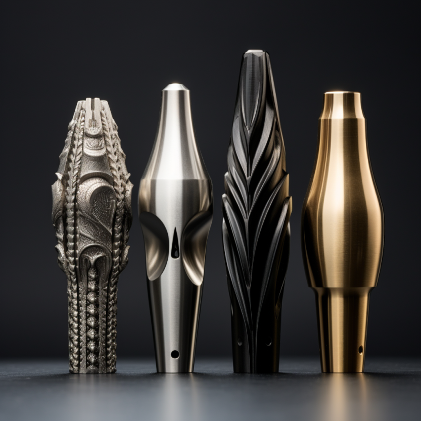
In some cases, an assembly may be composed of too many parts. The design engineer may find that handling and insertion times can be drastically reduced by combining parts to minimize flow times. Booker cautions that such redesigns may result in an excessively complex part replacing an otherwise simple set of parts [1]. As a result, assembly tolerances may be impossible to hold as the more complex part requires specialized tooling to produce. An example of this would be excessive overhanging features in additive manufacturing requiring support structures to be designed to allow for proper manufacture. If these overhanging features are placed as a separate part and then snapped or fastened into the original part, the additional support structures may be eliminated. This allows for a less complex design and a more straightforward manufacturing process, as the support structures will not have to be sanded down or chipped off.
Poka-yoke forms one of the main pillars of Design for Assembly. Poka-yoke is a design philosophy that incorporates error-proofing wherever possible. Asymmetric designs are promoted, as are designs that integrate alignment pins and color schemes. Assembly workers can work faster and with fewer errors as they have fewer decisions to make in the product manufacturing process. Booker states that the poka yoke may only be truly effective as a single solution whenever used on smaller assemblies.
Another critical aspect of the poka-yoke is ensuring that malformed parts are not allowed to reach the point where they are subject to quality inspection. Quality inspections are, by definition, non-value work and should be minimized. If no malformed parts are produced, quality inspections become unnecessary.
The design engineer can ensure quality inspection minimization by ensuring tight tolerances are only used wherever required. The design engineer must also validate that excessively tight tolerance requirements do not risk critical device functions such as loss of clearance through tolerance stacking or limited oil flow due to partial blockages. Overall, poka yoke may be one of the most critical aspects of Design for Assembly as it may be applied in every situation.
Another method by which parts may be error proofed is by self-location. Booker considers this one of the fundamental steps to take in Design for Assembly. Parts may be designed such that they are tapered, with only one end fitting into the correct slot. Alternatively, parts may be chamfered or filleted such that the proper orientation is evident to the assembly worker. Instead of chamfering, parts may have locator holes. Some parts may include indexing arrows or instructions machined onto the part's surface. For products with especially vital orientation, such as drill jigs, indexing pins may also be used to ensure the correct orientation of the part or product.
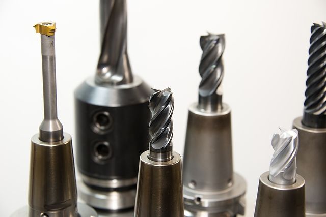
Fixturing is a valuable form of Design for Manufacturing that the engineer may overlook. A well-designed fixture prevents errors and significantly improves the build plan. Fixtures are tools that support and align a workpiece to undergo processing. The workpiece is typically clamped in place to restrict movement in some or all directions of translation and rotation. The workpiece must also be aligned to locating pins to ensure proper orientation. Finally, the workpiece will be placed on some type of support structure which further ensures correct orientation and provides a way for the forces of the machining processes to be transferred to the fixture apparatus. By providing a base for assembly, manufacturing times can be reduced.
In addition to fixturing design, workpieces may be attached to fixtures before machining and stored in Kanban containers. This allows the machinist to avoid setting the fixture up on their own. Through accomplishing this, a slowdown on the production line due to excessive machining times can be compensated for by reduced machining setup times.
Using these major tools, design engineers are better equipped to create parts and products cost-effectively. Parts and products incorporating Design for Assembly are easier to assemble, cheaper to produce, and less prone to defects. The criticality of error-proofing components before assembly to minimize non-conformances is of particular note. By making Design for Assembly part of every engineer's toolkit, companies may realize greater profits and higher customer satisfaction.
References:
[1] Booker, J., Swift, K., Brown, N., (2005), "Designing for Assembly Quality: Strategies, Guidelines, and Techniques," Journal of Engineering Design, 16 (3), pp. 279-95.


Member discussion