Design for Manufacturing: Boring
This article looks at the recommended design practices for boring machined parts.
Boring is the process of subtractive manufacturing where holes are enlarged. Boring allows for both cutting tapered holes as well as meeting exact tolerances. Boring allows for establishing high-quality surface finishes. Boring is expensive to perform and requires a highly trained operator to accomplish.
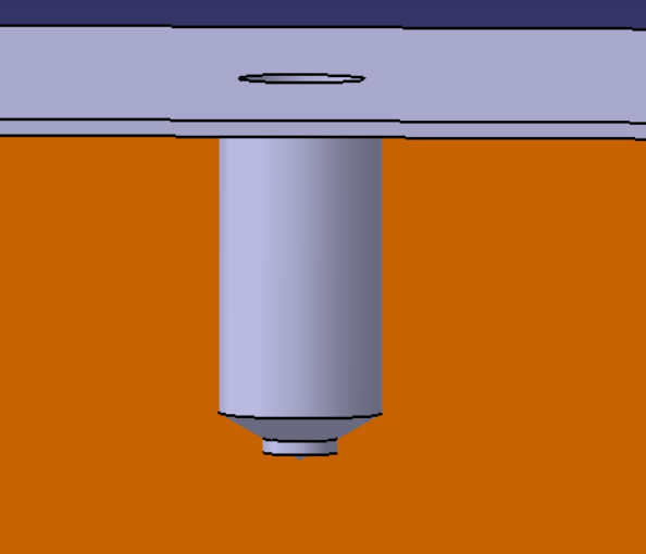
You should avoid the use of boring in workpieces that have interrupted surfaces. This causes mechanical shock to both the workpiece and the tool. You should also work to ensure that the depth-to-diameter ratio of boring does not exceed 4:1. This will cause boring bar deflection and result in accuracy loss.
For similar reasons to reaming, through holes should be preferred. Chip collection is vital to ensuring high-quality bored holes. Chip collection may be accomplished through an additional hole drilled to act as an area for chip storage until the hole can be cleaned.
Boring should only be accomplished on rigid materials at low risk of damage due to vibration. Boring causes a high amount of stress on the workpiece. Boring is also expensive relative to other machining methods and should be avoided unless required.
Key points:
(a) Avoid designing holes with interrupted surfaces.
(b) Avoid the use of a depth-to-diameter ratio of over 4:1.
(c) Preferentially design for through holes. If blind holes must be utilized in the design, design the blind hole such that there is a chip collection point of approximately 25% of the hole diameter
(d) Boring should be avoided whenever possible due to the expense associated.
(e) Only bore rigid materials not subject to vibration damage.
Use of this article will minimize costs, prevent tool damage due to chipping, prevent part damage due to vibration, prevent tolerance violation, and ensure that holes will not be produced out of round.

Member discussion