Communication Systems: Fundamentals and Power Conversion

Whenever considering what makes up a communications system, one must first look at the big picture before it's possible to zoom in on the individual components. The primary purpose of a communication system is to transmit information from a source to a destination. This is accomplished by using some form of transmission, some transmitting medium, and some type of receiving system.
In the case of standard computer networking, it is easiest to consider the source as the user running some applications on a computer endpoint. This application encrypts the data into whatever form is appropriate, deconstructs the message into packets and frames, and then transmits the information as binary pulses of electricity or light. Another computer will receive the binary pulses and reconstruct the original message.
Similarly, radio communication systems work in the same way. A message is recorded, modulated, transmitted, demodulated, and then reconstructed to play to the listener.
For this article to make sense, we must first understand the most powerful tool in our toolbox: The Fourier Transform.
By utilizing the Fourier transform, we can deconstruct signals into their frequency components. Similarly, using Fourier coefficient analysis, it is possible to reconstruct any message as a sum of sinusoidal waves.
What is a frequency component?
Consider a simple 60 Hz pure sine wave hypothetically coming from your wall outlet. This signal is around 170 Volts in amplitude from peak to trough. It averages around 120 Volts using the Root Mean Square method of determination. By using the Root Mean Square method, we get a much better idea of the value of a signal since the average value of any pure sinusoid is simply zero.
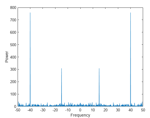
Returning to our pure sinusoid, we can perform a Fourier transform of this signal. We can use the integral method or look up the result in a Fourier transform table. Regardless of the process, the result will be two Dirac-delta impulses of half of our original amplitude, with one sitting at positive 60Hz and one at negative 60Hz.
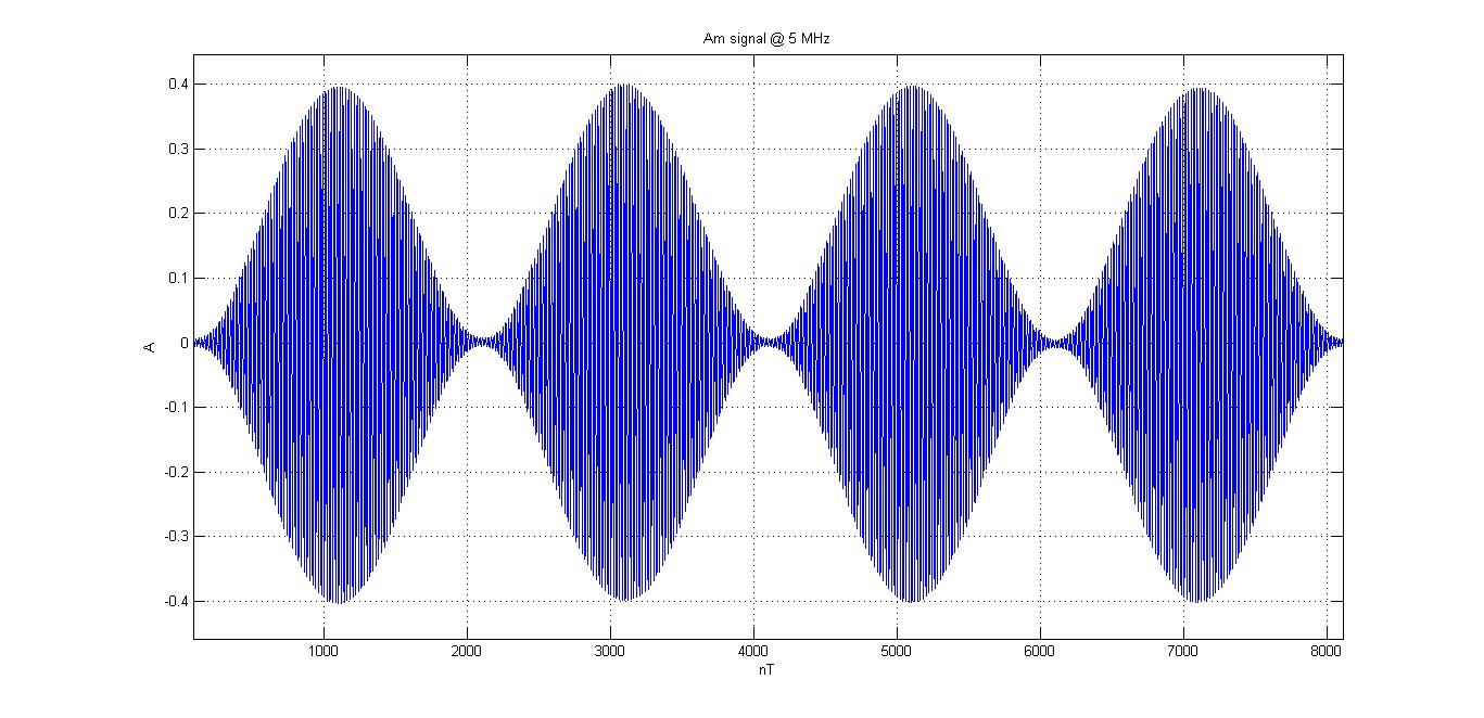
What does this tell us? Well, nothing that we shouldn't have expected. If our sinusoid is perfect, we'll see nothing but the two impulses at the correct frequencies. However, if our 60Hz sinusoid is somewhat modulated by another signal, we'll see harmonics develop further out.
We discussed some basic concepts and introduced the problem of power conversion and harmonics.
How do these harmonics develop?
Well, let's look at one common household situation:
In your computer, 120VAC 60Hz is converted into both 12VDC and 5VDC for your motherboard and other system components to use.
For the sake of argument, let's suppose we rectify and filter down to 12VDC.
How can we efficiently convert from 12VDC to 5VDC?
What if we want to convert from 5VDC back to 120VAC 60Hz?
Some might say that we could use a voltage divider circuit.
This would be correct if efficiency were not a concern. Unfortunately, we don't want inefficient electronics turning our valuable electricity into heat.

Voltage dividers work by tapping off a particular resistor node in a circuit composed of multiple resistors. The desired voltage can be obtained by balancing the values of the resistors proportionally to get the correctly proportioned voltage output. This works for us only so long as neither efficiency nor thermal waste is a concern. Also, voltage fluctuations at the input will cause similar fluctuations at the output.
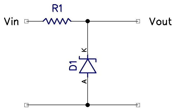
What about a similar circuit known as a linear regulator? These use diodes to achieve much the same effect. Instead of a voltage divider circuit, a current limiting resistor is placed in series with multiple diodes. Diodes, once fully conducting, tend to have a steady voltage drop across them. Typical values are around 0.7V. The desired voltage drop can be obtained by placing multiple diodes in series. By tapping off these diodes, a relatively constant voltage can be obtained. However, there are still a lot of thermal losses and inefficiency associated with this. More advanced forms of linear regulators will use one or more transistors to achieve a similar result (with less thermal losses).

The final solution we will look at is using a circuit called the "buck converter." This circuit uses high-speed switching circuits to charge and discharge capacitors and inductors. This allows for a highly efficient conversion from one voltage to another. The tradeoff for this is the introduction of a slight ripple in our output signal. It may be only a few millivolts; however, it is still enough to cause concern in some applications.

Similarly, a "boost converter" can convert from 5VDC to 12VDC. This works very similarly to the buck converter; however, the arrangement of components is somewhat different.
What if we are trying to instead convert our 12VDC back into 120VAC? That calls for a completely different type of circuit. In the case we'll consider now, we'll use pulse-width modulation. This will use a similar method to the buck converter, where high-speed switching allows multiple voltages to be output at a high rate of speed. By merging some aspects of the buck/boost converter with a comparator circuit, we can get something close to our desired signal. However, small ripples will be present that will produce the higher frequency harmonics we were worried about before.
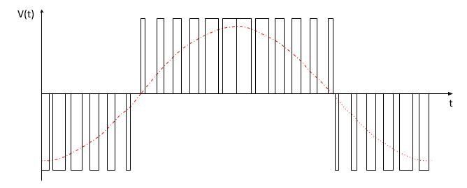
Returning to the original problem statement, imagine that our 60Hz sine wave is being produced using a 5Khz switching circuit from a pulse width modulator. Using a 3-stage pulse width modulator (Waveform seen above) will cause harmonics to form at around 10KHz and repeat out at much lower power levels much further up in frequency. By increasing the number of PWM stages and improving the filtering, we can get closer to our desired 60Hz sine wave.
We know that all of this exists by modulating our original input signal using the desired scheme and performing a Fourier analysis of the resulting equation. If we want a pure 60Hz sine wave coming out instead of the PWM signal, we can filter out the higher frequency harmonics using a low-pass or band-pass filter.
Next, we'll look at modulation schemes, multiplexing methods, and the associated distortion that sometimes happens.
Once you're comfortable with these topics, check out some more advanced communication theory.


Member discussion