Communication Systems: Amplitude Modulation, Multiplexing, and Distortion Filtering

Before reading this article, make sure you're familiar with communication systems basics.
This article will look primarily at the methods used for the modulation and demodulation of radio messages. We'll then discuss how signals can be multiplexed and demultiplexed. As a natural extension, we'll talk about the distortion that occurs and how we can resolve it.
Looking back at previous articles, one might wonder how this relates to the original point of figuring out how to get a signal from point A to point B. Without going into much detail regarding antenna design, we'd have to have a massive antenna to broadcast at anything approaching 60Hz. I'm talking hundreds or thousands of miles of cabling (like in the ELF project). There are innovative ways to do it using deep-drilled cabling in the Earth, but that's far out of reach for your average radio station. Even something as high as 10KHz would require an antenna about 17 miles long. Instead, we modulate our communications signals to very high frequencies so that our antennas can be more easily constructed.
How do we modulate our messages?
Amplitude Modulation
It just so happens that one of the simpler modulation methods is one of our oldest. Amplitude modulation is where the amplitude of our message is varied to modulate it to a higher frequency. Normally a message is modulated using a much higher frequency signal. There are several ways this can be accomplished.
Double sideband-suppressed carrier (DSB-SC)
This method uses only the upper and lower sidebands of the signal to pass a message. The carrier signal is suppressed which results in substantial power savings. However, in doing so, our bandwidth requirement is still relatively high. This is accomplished using a product modulator circuit to multiply our message signal by the carrier signal.
One of the most common product modulators is the ring modulator (a double-balanced modulator). This is a collection of diodes switched at a certain frequency to inject the carrier wave into the message. This is a similar process to electromechanical commutation.
For DSB-SC modulation, we use the following two equations for time and frequency domain representation.
S(t) = m(t) Ac cos(2pi fc t)
S(f) = ½ Ac [M(f-fc)+M(f+fc)
where
M is the shifted message convolved with each Fourier-domain Dirac-delta impulse
Ac is the amplitude of the carrier wave
fc is the frequency of the carrier wave
The higher frequency component is known as the upper sideband whereas the lower frequency component is known as the lower sideband. The two should be symmetric. If the message signal occurs at more than one frequency, that will result in multiple frequencies in each sideband.
One problem associated with DSB-SC modulation is the phase reversal that occurs to the message signal when the carrier signal waveform has a zero crossing at the half-cycle point. This causes the demodulation process to be slightly more complex to account for the phase reversal without losing message integrity.
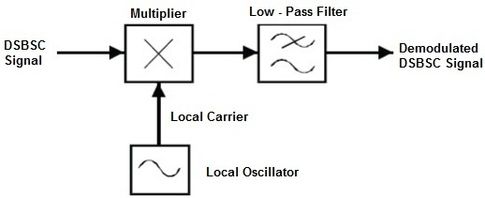
To demodulate a DSB-SC signal, another product modulator acting at the original carrier frequency must be used. This is combined with a low-pass filter to obtain the original message from the output of the product modulator.
Since the original carrier frequency may not be known, synchronization circuitry is required. One solution to this is the phase lock loop. The phase lock loop comprises a product modulator, low pass filter, and voltage-controlled oscillator. The voltage-controlled oscillator acts as a sinusoidal generator where the output is determined by the voltage applied to the input. The VCO output is adjusted such that with a zero input signal, the output signal is 90 degrees out of phase with the detected carrier signal. This is accomplished by isolating the carrier signal with a bandpass filter and feeding it back into the phase lock loop as a pilot signal. If isolation of the carrier signal isn't possible, it is possible to use a Costas loop instead. This uses a phase discriminator to approximate the carrier signal.
Double sideband-large carrier (DSB-LC)
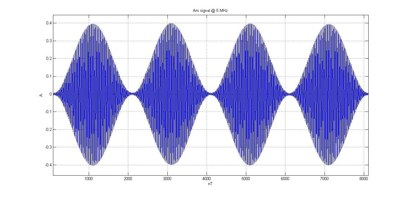
This is the standard broadcast AM that we're all used to. DSB-LC modulation works by adding a DC offset to our message signal before performing DSB-SC modulation. This results in the carrier signal showing up in the final signal waveform. This results in an"enveloping" effect.
s(t) = Ac[1+u*cos(2 pi fm t) cos (2 pi fc t)
where
u is the modulation index found by multiplying the amplitude of the message signal times the amplitude sensitivity
This amplitude sensitivity is chosen based on the scaling of the original DSB-SC signal compared to the carrier envelope it is placed within. The modulation index, u, can also be calculated by the equation u = (max amplitude - min amplitude) / (max amplitude + minimum amplitude).
The benefit of this modulation method is that phase reversals only occur during over-modulation conditions which simplifies the demodulation process. The primary downside of this modulation scheme is that most of the signal power is wasted in the carrier signal. This requires extra amplification during demodulation.
Demodulation can be accomplished using the synchronous detection techniques discussed for DSB-SC; however, a simpler method exists called "envelope detection." This can be a half-wave rectifier with a parallel RC circuit filter. On positive half-cycles, the capacitor will be charged. As the signal falls off, the diode will block the signal and allow the capacitor to slowly discharge through the resistor until the next peak event. This will "smooth" the waveform out until only the original message signal remains. If necessary, a series capacitor/buffering circuit can be used to remove the DC offset and obtain the exact message signal.
Single-sideband (SSB) modulation
Single-sideband modulation is where the modulated wave only has the upper or the lower sideband. This is especially well suited to voice signal transmission as the frequency content of the human voice has a large energy gap between 0 and 200Hz. This modulation method requires the lowest amount of power and bandwidth; however, it also has a relatively high complexity associated with modulation and demodulation.
The theoretically easiest way to create an SSB-modulated signal is to create a DSB-SC signal and then suppress one sideband by filtering it out. However, this requires an extremely accurate filter which may be prohibitive.
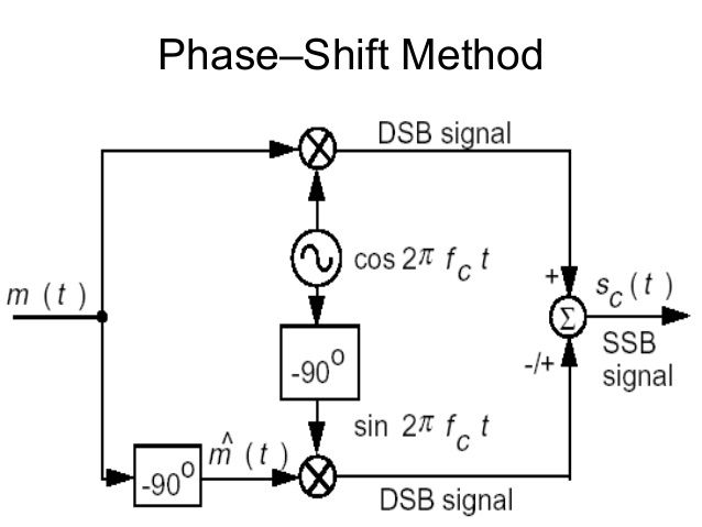
Realistically, it is easier to construct a circuit that duplicates the DSB-SC signal and phase shifts it by 90 degrees. It is then combined with the original signal to cancel one sideband completely. The downside to this method is that the circuit will only work for a small bandwidth of signals without being reconfigured.
Vestigial sideband (VSB) modulation
This method of modulation uses one single sideband to transmit a message. This is useful mainly for transmitting television signals due to the wideband nature of the signal.
This modulation method consumes less bandwidth compared to DSB-LC while still allowing for the use of an envelope detector for demodulation.
To create a VSB signal, the same method of producing a DSB-SC signal is followed with one exception: a sideband shaping filter. This allows the inner or outer sidebands to be reduced in amplitude which causes a corresponding reduction in bandwidth requirements. As a result, bandwidth-intense applications can be made to fit in a smaller frequency range.
Next we'll look at multiplexing methods and the associated distortion that sometimes happens.
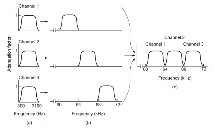
Multiplexing is the method by which multiple signals can be combined into one signal to save power or bandwidth.
There are two primary methods of multiplexing used in communication systems.
Frequency Division Multiplexing is where each frequency is assigned to a particular sender.
Time Division Multiplexing is where each time slot is assigned to a particular message sender.
To understand TDM a little better, consider a 24-voice channel T1 line. There are 25 total time slots in each transmission cycle. Each voice channel gets one time slot while the final position is given to a synchronizing bit. This allows simultaneous transmission of multiple channels that can be relatively easily decoded at the receiving stations.
Frequency Division Multiplexing allows multiple signals at different carrier frequencies to be broadcast simultaneously. So long as each carrier signal is significantly different than the other carrier signal, no overlap will occur. When designing such a system, the Fourier-domain representation of each signal must be carefully considered to ensure sufficient space exists for each signal. Standard broadcast FM is the most commonly encountered form of FDM.
Next, we'll look at the distortion that sometimes happens when working with our communications signals.
Two primary types of distortion occur within a communication filtering system
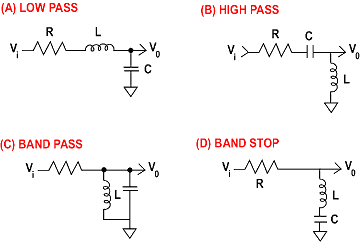
Amplitude distortion occurs when the amplitude is scaled as it transits the system. This is easiest to imagine in a high pass filter causing lower frequency components of a signal to be degraded. In an HPF described by H(f) = jf/(100+jf), frequency components at 500Hz lose about 2% of their amplitude while frequency components at 100Hz lose 29% of their original amplitude.
Phase distortion occurs when the phase of a signal is delayed as it transits the system in question. For example, a high pass filter can cause a substantial phase delay for low-frequency components of the signal in question. In an HPF described by H(f) = jf/(100+jf), a 27-degree phase delay happens for frequency components at 200Hz, while a 45-degree phase delay happens for frequency components at 100Hz.
Distortion can be compensated by using an equalizer. You may be familiar with these from your home audio system. An equalizer is placed in series with the signal to counteract the effects of filtering on the channel such that the channel appears to be free of distortion.
Another point for consideration is harmonics produced by non-linear filtering. A non-linear filter will contain frequency components not originally contained within the input. These frequencies will manifest at the harmonic frequencies for the original frequency. These harmonic frequencies can be filtered out; however, some harmonic distortion will still be present due to this signal degradation. The signal harmonics distortion ratio is the ratio of the amplitude of the harmonic frequencies compared to the original fundamental frequency.


Member discussion