How To Build Your Own Motor

Magnetism is something that never fails to amaze me. Have you ever wanted to make your own small electric motor?
It's fairly simple to do. The end product of this project is a basic motor, some sparks, and a bit of knowledge. I've included links to buy the less common items from Amazon via my affiliate program.
Bill of Materials:
-Wire strippers (scissors will work in a pinch!)
-Alligator clips with jumper wires
-Plastic cup
-D cell battery
-Rubber bands
-2 paper clips
-2 rare earth type magnets
-Permanent marker (Sharpie works best)
-Thin, insulated wire (Enameled works best since it weighs less but I didn't have any laying around. Your armature has to be properly balanced to spin. Rubber-insulated wire weighs more which reduces your tolerance for balance.)

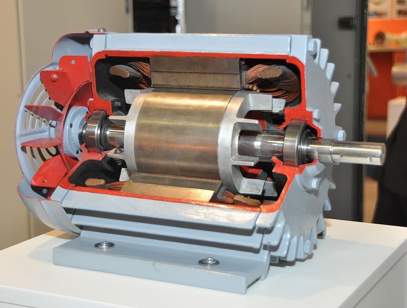
I'm going to talk about motor theory briefly. When a current flows through a conductor, an electromagnetic field is developed around the conductor. If you make a thumbs-up sign with your fist around the wire with your thumb pointing in the direction of current flow, the curve of your fingers will point in the direction of electromagnetic field rotation. This is one of your Right Hand Rules. That electromagnetic field is the star of this show. Our disk magnets are going to interact with the electromagnetic field we're going to create with our wire and battery.
Step 1: Build the commutator. Kind of. In a real DC motor, a commutator device exists to swap input polarities going into the armature. By doing this, it allows the magnetic field to attract where it needs to attract and repel where it needs to repel. Normally we would be using carbon brushes and slotted copper bars.
Unfortunately, we're going to reproduce that with paper clips and markers. Using the wire strippers, remove the insulation from the ends of our wire. If you're using enameled wire, use sandpaper. Now draw half of the insulation back on using a permanent marker. This will reduce the torque by about half, but luckily we're just doing this for fun rather than trying to supply coolant to a power plant or something. This creates an insulated layer on the side of the wire to help our commutation.
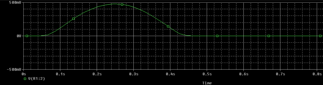
For electrical engineers playing at home, this changes our effective input waveform from a straight DC signal to a square wave with a 50% duty cycle. Half the time, the armature will receive an impulse. If you're trying to model this mathematically (because you hate fun and love MATLAB), use a unit-step equation.
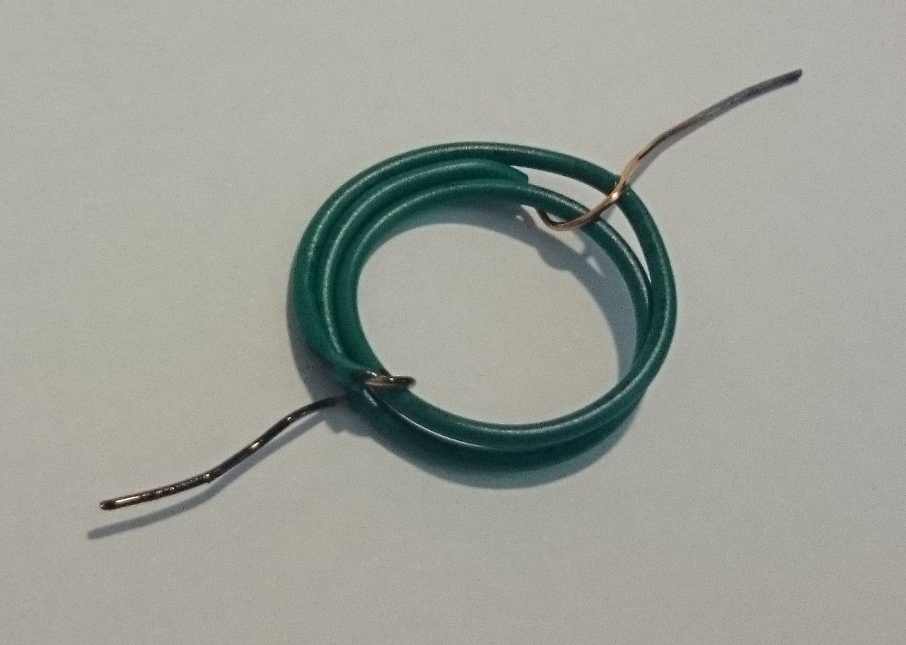
Step 2: Wrap the wire around the battery repeatedly. This is building the armature for our motor. Start in the middle of your wire so that you end up with about 3 inches of leftover wire coming off each side of the battery. You might find yourself doing this several times since balance is key.
Step 3: Slip the free ends through the armature and tie them off to hold the coil together. You should have a secure series of loops left over.
Step 5: With the armature all but done, let's focus on building the stator. For this, we're going to take our disk magnets and put one under the cup on the bottom and the other one inside the cup on the bottom. The magnetic fields will attract each other and keep them together. Place the mouth of the cup down so that it is on the bottom.
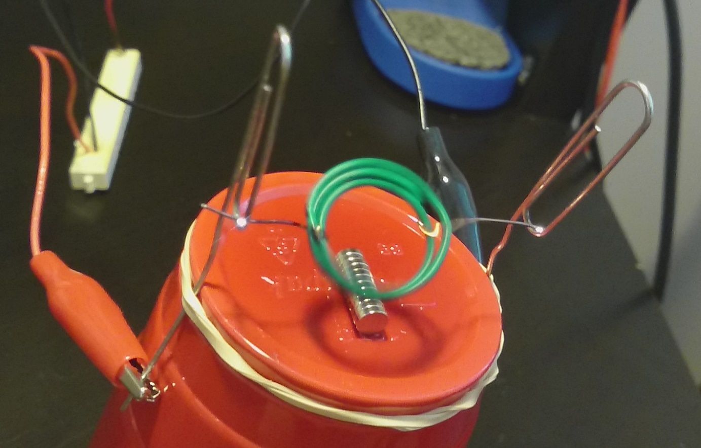
Step 6: It's time to make our slip ring assembly. We're not going to use anything fancy, just paper clips. Bend the paperclips into a P shape, press them against opposing sides of the cup, and rubberband them into place. The goal is to make it so that the ends of the coil we previously made can hang between the clips above our magnet. Hang it there right now.
Step 7: Clip the alligator clips to the paperclip ends and attach the jumper wire to the D cell battery.
Step 8: Watch your motor spin. If it just twitches, the balance is off. Since adding weight shims isn't practical, try bending the loop for a better balance. Be careful touching everything because it will get hot!


Member discussion