How do you build a flashing LED circuit?
This is the first of many tutorials on making certain electronic circuits. In programming, it's traditional to start with a "Hello, world" project.
This project will follow that tradition by creating a blinking LED using a 555 timer set up for astable operation.
We'll also look at some basic theory behind the operation of this circuit and the output on an oscilloscope. I've included Amazon links for every component necessary for this project. To reduce the cost, desolder components from other projects or old electronics. No soldering is required for this project.
First, let's get our materials organized:
1x 555 timer
1x 4.7uF capacitor, electrolytic (here is a link to a box of 100 random value capacitors for 11$. Alternatively, desolder something from an old motherboard)
1x 100k ohm resistor (here is a bag of 500 resistors of all common sizes from Sparkfun via Amazon)
2x 1k ohm resistor
1x 220-ohm resistor (doesn't have to be exact, any valid current limiting resistor for a LED will work)
1x LED
1x bipolar junction transistor (NPN)
1x breadboard
1x DC power supply (a 9V battery also works. Get the terminal connector here)
1x jumper wire kit (consider this or this)
For this project, I am using this DC power supply created from a kit. You can use a 9-volt battery with the connector I linked in the materials section. I am also using this oscilloscope to provide the digital output that you see later on in the article.
Alright, the first thing to do is lay out your materials in an organized fashion. Make sure you don't mix up your resistors. You can always use your multimeter to check resistance values if using resistor code is too cumbersome.
As a quick aside, Fluke multimeters are the absolute top-of-the-line and I avoid using anything that isn't from them. If you're touching leads to anything above 30 volts, you want the safest, most reliable gear. If my current Fluke fails, I'm replacing it with this multimeter.
Fanboy? A little.
They've saved my life quite a few times, after all.
[caption id="attachment_632" align="alignleft" width="714"]
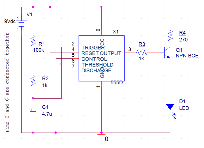
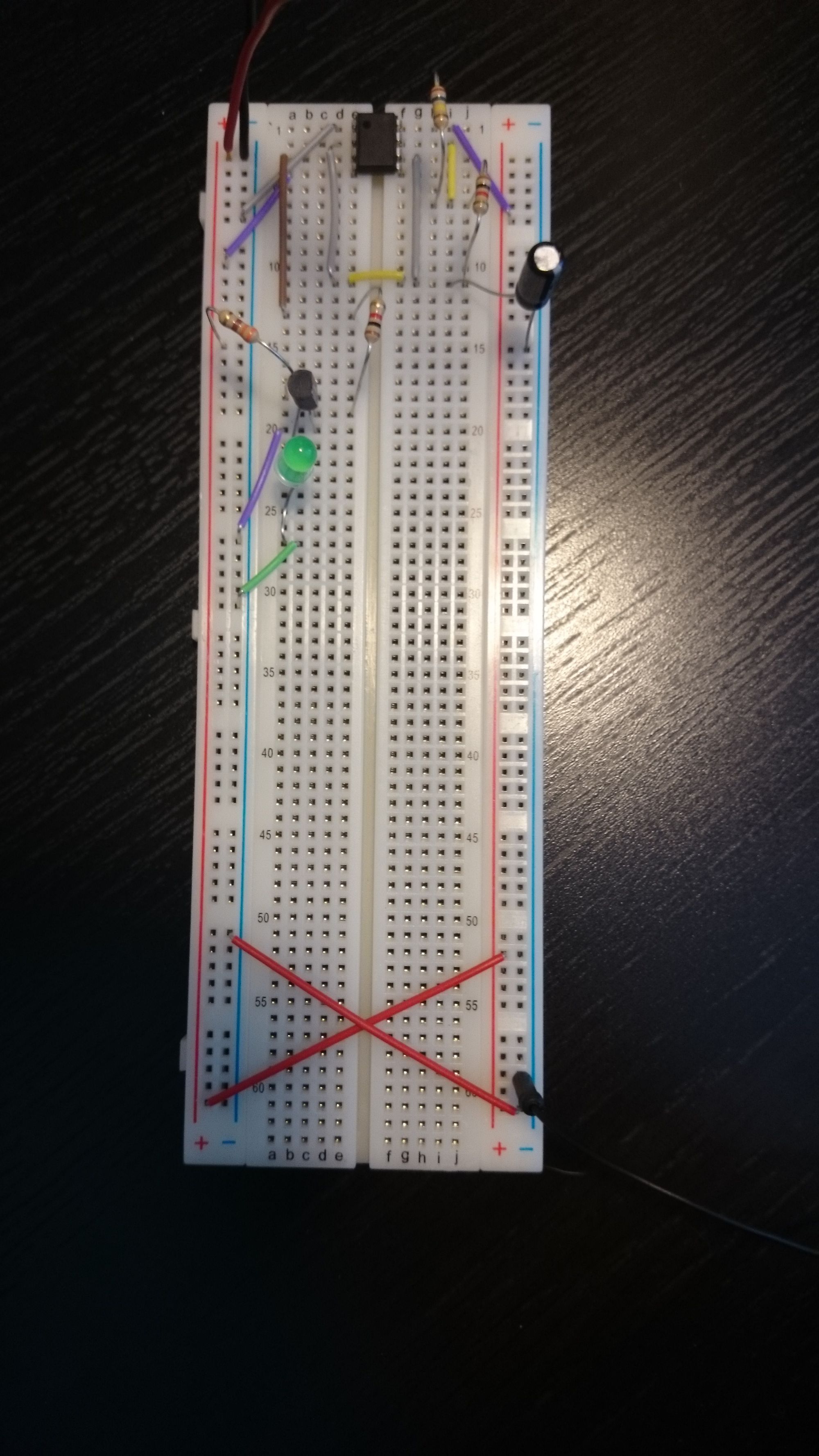
Let's start wiring this puppy up. Place your components on your breadboard similarly to how I have. You want the 555 timer to straddle the blank channel on the breadboard so you don't internally short two pins across the breadboard backing.
Alright, I'm assuming you've placed your components approximately the same as my picture and schematic. Place your wires in the same way. Make sure that every connection is secure. WARNING: Make sure the "- - - - - -" negative pin of the electrolytic capacitor is wired to the ground and not the other way around.
Otherwise, it will explode.
I still have nightmares about TAing a freshman electrical lab where at least two capacitors exploded daily.
Now that you're wired up, turn that puppy on.
In an ideal world, you're now staring at a blinking LED.
In a less-than-ideal world, your capacitor exploded because you wired it backward.
Live and learn!
Consider now what's going on under the hood.

Pin-1 of the 555 timer is your ground pin. That's fairly self-explanatory. Everything needs a path for the return current flow.
Pin-2 is your trigger pin. This pin controls the output and timing cycle for the 555. Whenever the trigger input drops from >66% of the supply voltage to <33%, the trigger is actuated, and pin-3 will output a "high" signal.
Pin-3 is your output pin. This is what you hook your BJT to so that it can gate power to your LED.
Pin-4 is the reset pin. This will be connected to the VCC since we're not using it.
Pin-5 is your control pin. We're not going to use this either. If erratic triggering from noise is a problem, install a coupling capacitor. That's just a very low-value capacitor used in filtering.
Pin-6 is the threshold pin. This functions exactly the same as your trigger pin, except it causes pin-3 to output a "low" signal instead.
Pin-7 is your discharge pin. This will act to discharge your capacitor
Pin-8 is your VCC pin. This provides your main power to the 555. VCC needs to be between 5+ and 15+ volts.
With this in mind, let's briefly discuss how your flasher circuit works.
Your capacitor will charge with power supplied through R1 and R2.
Remember that the time constant equation is TimeConstant=RC.
Five time constants are required to fully charge the capacitor, in case you forgot.
Once our discharge pin is triggered, the capacitor will discharge only through R2.
The capacitor voltage will determine the output pin via the trigger and threshold functions as discussed above.
Cool, right? Alright, since I love math, let's throw some equations around then call it a day.
Your frequency (in hertz) works out to this equation:
f = 1 / (ln(2)CR1+2R2))
The period of our waveform is just the reciprocal of frequency: p=1/f
Our duty cycle (percent of time that we have a "high" output in the wave function) is:
D = (R1+R2)/(R1+2*R2)


Member discussion