Digital Logic and Boolean Algebra

Boolean algebra is a topic that is extraordinarily important in the electronics business.
Why is that, you ask?
Well, Boolean algebra yields Boolean logic. Boolean logic is how computers think. To create a circuit that beeps an alarm when your car door is open but not when the engine is running, we need combinational Boolean logic to construct digital logic gates in the correct configuration to make the magic happen. We also need to understand Boolean algebra to program in assembly language.
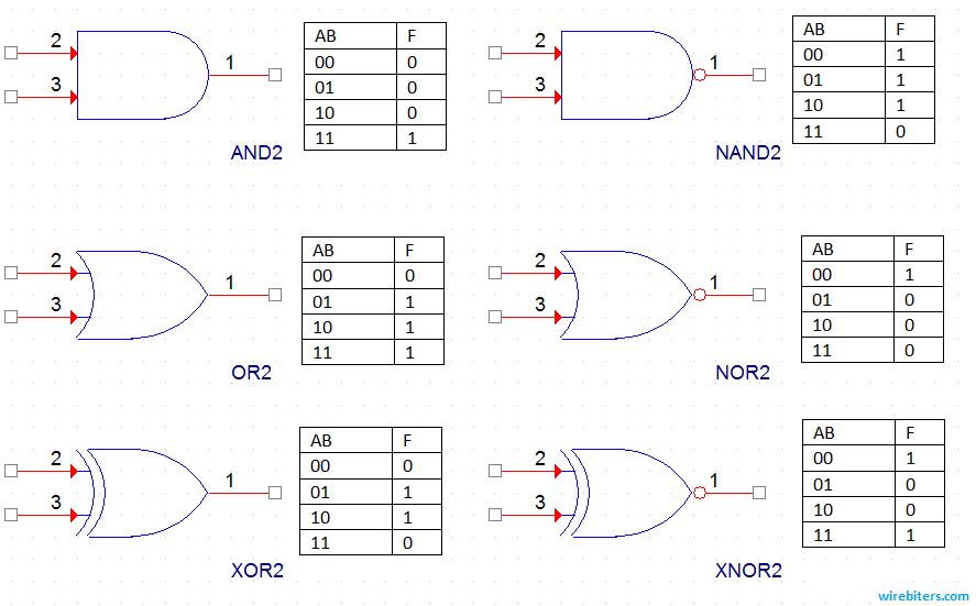
Let's first look at the meat and potatoes of logic gates:
AND gates: These take two or more signals and output a binary "true" signal if all input signals are "true"
OR gates: These are the same as AND gates, except they only require one input signal to be true
NAND gates: These are the same as AND gates, except instead of outputting a "true" when all inputs are true, it outputs a "false." Using deMorgan's theorem, these can reduce the transistor count of a digital system, making it cheaper to produce. NAND and NOR gates use fewer transistors than other types of logic gates.
NOR gates: This operates the same way as an OR gate except outputs a "false" instead of "true." These are also used in the same way as deMorgan's theorem.
XOR gates: These will output a "true" signal only if one and only one input is "true." To help you remember, the X stands for "exclusive."
XNOR gates: These function the same as XOR gates except output a "false" instead of a "true" and "true" instead of false.
Whenever we calculate a Boolean expression to describe a system, we use certain operators to describe it. The multiplication "*" describes an AND gate, while a "+" describes an OR gate.
Using a single ' mark indicates the opposite of a given signal. For example, A' means the opposite of what A is.
If your digital signal from A is 0, A' would be 1.
The term for taking the inverse of a digital value is taking its "compliment." Another way to say this is "the complement of A is A not."
Let's say that our function is described by
F = A+BC'
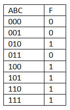
We get the above truth table if we write out all possible combinations of A, B, and C. This truth table indicates that we only get a "true" output when both A and C are 0, and B is 1 or any situation where A is 1.
What could that function describe? Suppose you wanted an alarm to go off when the door of your car is open (A) or if a person sitting in a car seat (B) doesn't have their seatbelt on (C). If the seatbelt is fastened, C' will be 0, meaning no alarm signal is sent, assuming the door is shut. If no one is sitting in the seat, B is zero, so no alarm signal will be sent unless the door is open.
How do you make this circuit work? Easy!

This is how a logic circuit would be wired up in a schematic. This particular image was generated using the electrical engineering application known as PSpice. The particular components I selected use 2 and 3 as the input pins and 1 as the output pin. In real applications, there would also be pins for the power supply and ground for the logic chip. Also, the actual chips being used would be NAND gates. I'll explain why in my article on DeMorgan's Theorem. Until then, practice some equations and truth tables.


Member discussion