Axiomatic Design Reviews for Common Circuit Boards

Axiomatic Design of FTDI Board
FTDI boards are used to accomplish level shifting of digital signals. This is especially useful in converting USB devices to UART devices. FTDI boards make use of the USB protocol stack to allow computing systems to communicate with registered devices. As a result, automatic identification of many hardware devices is possible. Figure 1 demonstrates a functional block diagram of an FTDI USB board.
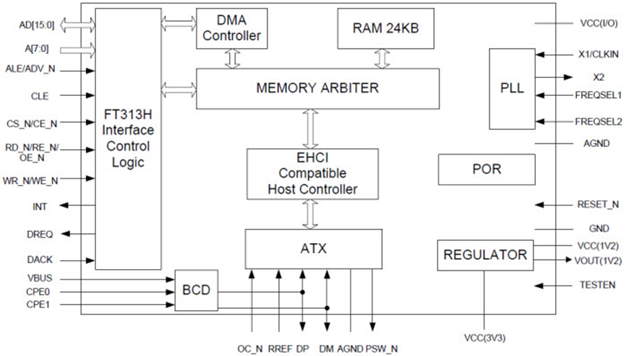
This circuit board is popular used as an interface between personal computers and off-the-shelf hardware such as keyboards and other human interface devices. Additionally, this circuit board bridges the gap between 3.3VDC and 5VDC systems by providing a service known as voltage shifting.
The functional requirements are:
FR1 = Provide voltage level shifting
FR 2 = Provide hardware UIDs to the host
The design parameters are:
DP1 = logic level voltage conversion
DP2 = USB protocol translation
The design equation may be written as:
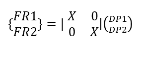
This is an example of an uncoupled design.
Axiomatic Design of Regulated DC Source Test Equipment
Test equipment regularly makes use of a regulated direct current voltage source in order to scale input voltages between multiple values. As a result, the step response of a circuit may be determined based on applying a given voltage and observing either the steady state or transient response. Additionally, trip setpoints of bistables present in equipment are possible by scrolling the DC source through a range of voltage values to ensure proper trip points are both in use and calibrated correctly [3]. The function of a standard switch mode power supply DC source can be seen in Figure 2.
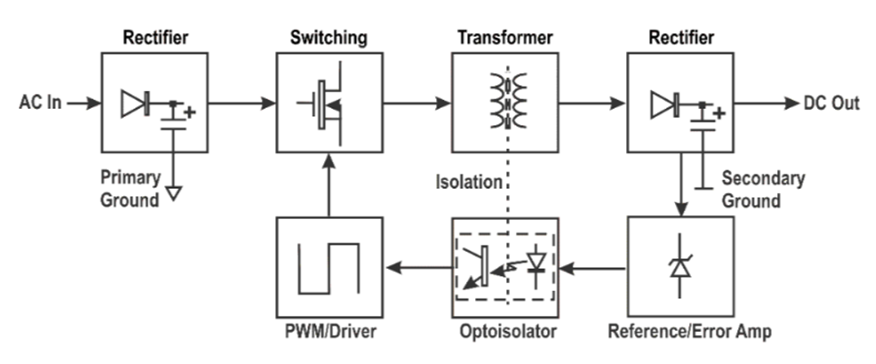
This system receives an AC input signal, rectifies it to a pulsing DC signal then smooths that based on a PWM-driven oscillator that controls the charge/discharge cycle of inductors and capacitors. The PWM circuit is controlled by a user-selected reference signal. The PWM signal is isolated from the primary signal.
The functional requirements are:
FR1 = Provide regulated output voltage based on user command
FR2 = Provide constant current source based on user command
FR3 = Provide isolation between input and output
The design parameters are:
DP1 = Regulation percentage
DP2 = Current limiting tolerance
DP3 = Isolation rating
The design equation may be written as:
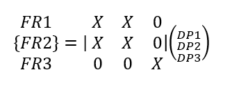
This is an example of a decoupled design.
Axiomatic Design of D’Arsonval Meter
The purpose of a D’Arsonval galvanometer is to provide a simple method of measuring electrical current. This system was developed in the early 1800s to assist in electrical experiments by Jacques-Arsene D’Arsonval. Although this may seem a primitive method of measuring current flow, the solid principles upon which it was designed result in the galvanometer still seeing regular use in modern low-cost applications. A block diagram of the operation of a galvanometer may be seen in Figure 3.
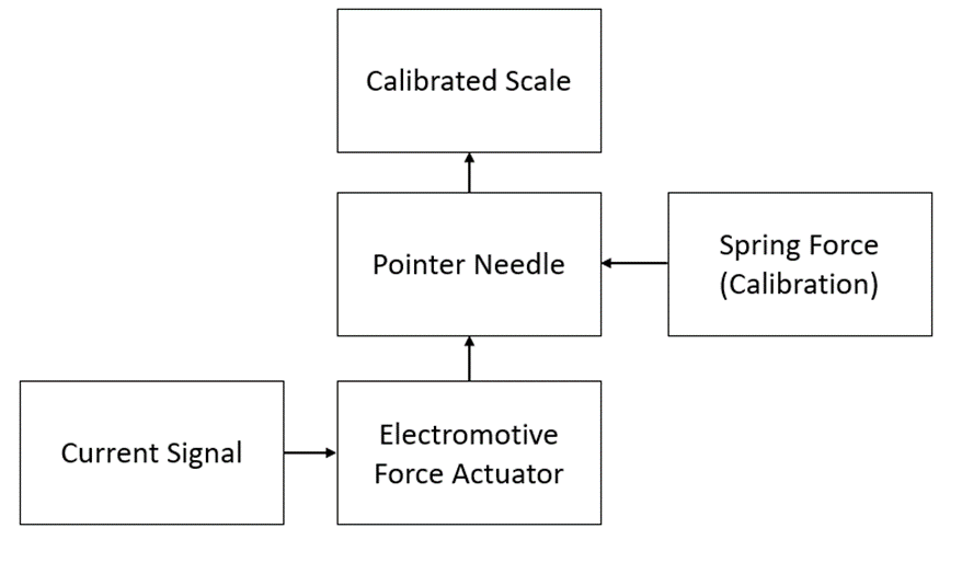
This system receives input from a current source which pushes on an electromechanical actuator. This actuator force is opposed by a calibrated spring. The resulting net force causes deflection on a meter which is displayed against a scale.
The functional requirements are:
FR1 = Provide visual indication of current
FR2 = Provides a method to calibrate the system by the end-user
The design parameters are:
DP1 = Actuator force strength
DP2 = Spring tension force
The design equation may be written as:
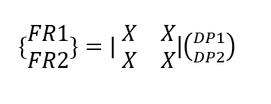
This is an example of a coupled design.
References:
[2] Mouser.com, 2016, “FTDI FT313H Block Diagram,” from http://www.mouser.com/images/microsites/FTDI_FT313H_blkdia.jpg
[3] Krein, P., 2015, The Elements of Power Electronics, 2nd ed., Oxford Press, New York, NY.
[4] ZL2PD.com, 2016, “Switchmode Power Supply Basics,” from http://www.zl2pd.com/img/smps/smps_block.gif


Member discussion