What does an Op Amp do?
I wanted to cover some basic microchips that any hobbyist or engineer should have in their parts bin. What do you do if you have too low of a voltage applied to something? Suppose you have a clock signal that isn't at the threshold needed to make your digital logic array work. You could use an op-amp!
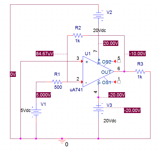
What is an op-amp? Well, the full name of the "operational amplifier" doesn't tell you that much. Fundamentally, they are solid-state microchips that use analog components to accomplish a particular goal. Most are used to supply an amplified voltage to a specific source. Above is shown a typical "inverting amplifier" with a gain of 2. First, let's think about what this little bit of silicon does.
They look like generic microchips. The above link is for the two-per-chip design.
Pin1/5: These are for the offset voltage for the chip. If you need a precise voltage output, this is your adjustment tool.
Pin2: This is your negative input. Sometimes people call this V-n.
Pin3: This is the same as Pin2 except for the positive. They are also called V-p. V-n and V-p are always equal in magnitude.
Pin4/7: Negative and positive power rails. Note that the output voltage can never go above its respective polarity's power rail value. In this example, the op-amp will saturate and not go above 20VDC or below -20VDC.
Pin6: This is the output of the op-amp. Note that it is connected to either V-n or V-p, depending on if it is configured for inverting or non-inverting. This particular op-amp is inverting. To make it non-inverting would require swapping the input ground and the input voltage source.
How do we know that the gain is 2?
Well, we know two fundamental truths. The input currents are effectively zero. The input voltages must be matched if the op-amp is operating normally. This is part of why we call it the "magic Dorito" chip. How does it do it? About two dozen transistors are squeezed inside that bad boy.
We now do a simple nodal analysis, do some algebra, and get Vout = Vin (R2/R1)
There are many possible op-amp configurations, and it is not feasible to memorize every combination. It's my recommendation to do a nodal analysis. Some op-amps act to sum their inputs, and some will provide the difference. Some can give the derivative of voltage change, while others can provide an integral of the input. Â These would require a more complex analysis technique. If R2 (also denoted as Rf) also has a capacitor hanging around nearby, it's probably one of those calculus function op-amps. There are dozens of other types of op-amp circuits available for use.


Member discussion