Design for Manufacturing: Sheet Metal Bend Reliefs
Sheet metal is frequently used in building both products and manufacturing machinery. Improper bending of sheet metal can cause material flow problems in soft materials and fracturing in hard materials. This article examines two tips for ensuring high-quality sheet metal in finished products.

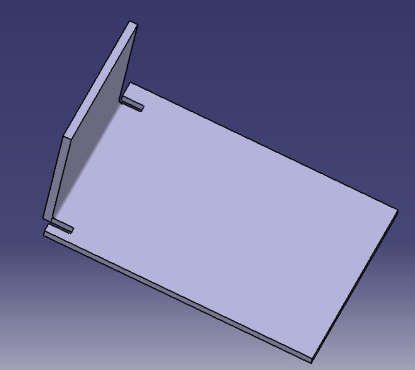
Lack of proper bend reliefs may cause material tearing due to localized stresses. This tearing is most prevalent along the major axis perpendicular to the bend. The most susceptible shape can be described as any segment of material that is being bent along an axis where there is a sharp corner orthogonal to that axis.
This shape can be visualized as bending one line segment in a T to the maximum depth permitted. Each corner of the T is at risk of tearing if the relevant line segment is bent without proper bend relief. See the picture on the side for an example.
Similarly, insufficient bend radius may lead to brittle fracture failure of the sheet metal. This is due to excessive localized stresses from the work-hardening forces imposed on the metal. This will lead to high residual stress in the material, which causes the material to require less tensile stress to reach the net stress required for fracture.

While designing products that incorporate sheet metal with bends, consider if the bends are located at points where a sharp corner will be created. These places are at a high risk of tearing. Two things can be done to reduce the risk of sheet metal tearing. First, utilize a minimal internal bend radius equal to material thickness. You should also incorporate bend relief cuts with a thickness of at least the thickness of the material, with a strong preference for bend relief cuts of a thickness equal to material thickness plus 1/64 inches.

Member discussion