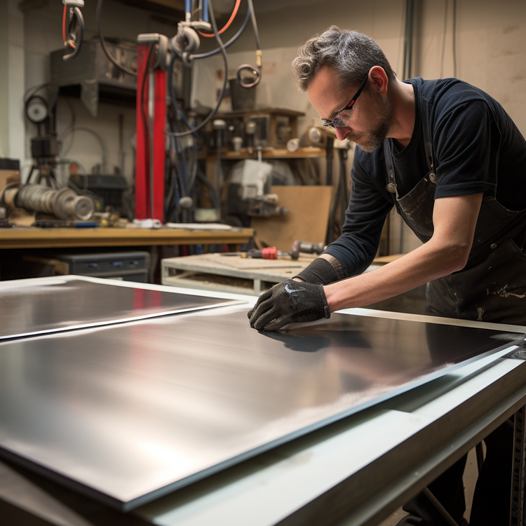
Design for Manufacturing: Grinding
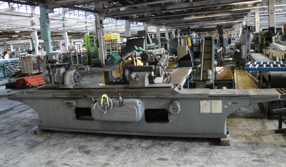
Grinding is a subtractive process that utilizes an abrasive wheel to remove material from a workpiece. Design engineers must remain cognizant of the limitations of this subtractive manufacturing process. Ignoring the limitations of this technology will result in excessive machine setup times as well as high costs from utilizing specialized tooling. Center-type grinders are subtractive manufacturing machines where the workpiece is held in place and rotated by the use of lathe-style pointed centers. These centers clamp the workpiece in place while allowing it to rotate along the same axis as the grinding wheel.
When grinding, it is vital to ensure that both the workpiece and the abrasive wheel have a free range of motion along the respective axis of rotation. If a workpiece has been manufactured such that a nonstandard center hole is present, the workpiece may have an unbalanced rotation or may not react appropriately to the grinding wheel.

When fine detail is required from grinding, design engineers should ensure that the center holes are lapped to an accurate 60-degree angle before being placed on the grinder. This ensures the proper performance of the machine on the workpiece. Failure to accomplish this may result in a workpiece that does not meet tolerances and must be reworked or rejected.
If you're going to use grinding in your machining process, you should consider:
(a) Designing the workpiece such that 60-degree center holes are present.
(b) Ensure that the holes are uniform.
(c) Lap the holes to correct any changes that may occur after heat treating the material if applicable
Following these guidelines minimizes the chance of part failure and tolerance rejection, which results in lower manufacturing costs and fewer instances of rework.
Grinders typically act perpendicular to the workpiece being acted upon. This process allows for high-quality finishes to be established by the machinist working the part. However, design engineers may erroneously call for undercuts to be put in through grinding. The limitations of grinding may not be obvious; however, undercuts are one machining operation that will only see limited success from grinding.
In order to grind in an undercut, the abrasive wheel must be skewed at an angle to the workpiece. It then must be trued in a way that permits the grinding wheel to come into contact with the workpiece at the correct angle to establish the undercut. This is a difficult task that requires high precision. Ultimately, more complicated undercuts, such as that seen below, will require a different machining process such as internal grinding.

Some additional points to consider:
(a) Avoid the use of undercuts in all situations
(b) If undercuts cannot be avoided, specify that the abrasive wheel is to be turned at an angle and trued such that an angled undercut is possible
(c) If a larger undercut is required, utilize internal grinding methods.
Following these guidelines avoids creating impossible geometry in many situations. Additionally, following these guidelines also minimizes the chance of using costly special tooling to create undercuts via grinding. This reduces part cost and tooling setup times.
Grinding is subject to some limitations that design engineers must be cognizant of. Workpieces must be well balanced as they will be rotated. Workpieces must have holes drilled for the grinder holders to attach to. Workpieces are also subject to geometrical restrictions based on what can be performed by grinding.

Attempting to grind a part that is more than twenty times longer than its own diameter will likely lead to part failure. This is due to the tendency of the part to bow when subjected to the force of the grinder. Additionally, designing parts with tapered grooves, angular undercuts, and variable radii, all impose additional tooling costs and complexity. Some of the aforementioned grinding processes are possible with specialized tooling; however, angular undercuts require additional process steps to create.
Final points for consideration:
(a) Ensure that parts are well balanced.
(b) Avoid the use of small diameter parts that are excessively long
(c) Avoid designs with grooves created by grinding.
(d) Avoid angular shapes and tapering.
(e) Avoid variable radii created by grinding.
Following these last points minimizes the chance of part failure during the manufacturing process. This also minimizes the chance of part deflection and maximizes the benefit of grinding. Fewer part failures result in lower overall manufacturing costs.
Featured image courtesy of Wikimedia User Three-quarter-ten licensed under CC BY-SA 3.0

Member discussion