Understanding CAD Surface Geometry
Computer-aided drafting software utilizes two main approaches to creating models: solid and surface modeling. Most individuals are first trained on solid modeling (extrusions, draft angles, pocketing, padding, etc.). However, many people stop there without going any further. Surface geometry workbenches are available in most modern modeling systems. These systems allow the end-user to create 3d models from 2d surfaces. First, let's look at some nomenclature.
Planar surfaces describe the infinite plane created by three non-coincident points. Planar surfaces are typically used to describe the origination point and relative geometry of sketches in certain CAD systems. Planar surfaces are the preferred method of creating relational designs due to the ease by which the offset amounts may be modified to change overall part geometry quickly. Planar surfaces are the default geometry found in most CAD programs and are typically available for editing in all workbenches as applicable.
The following are examples of using common surfaced-based geometry to create solid features:
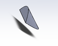
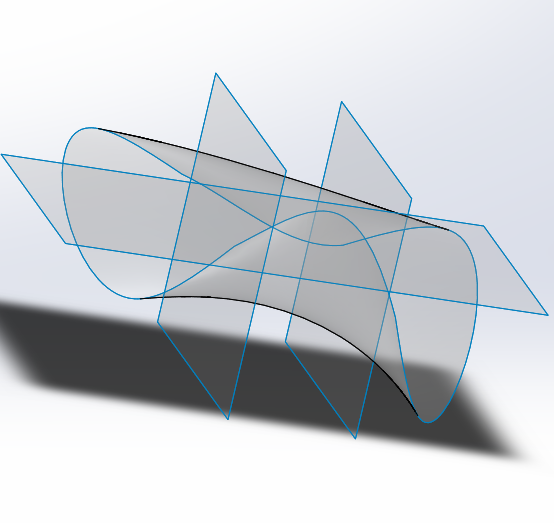
Lofted surfaces are planar surfaces created from curves. Lofted surfaces are typically used to generate solid geometry, such as pipes and airframe components on airplanes.
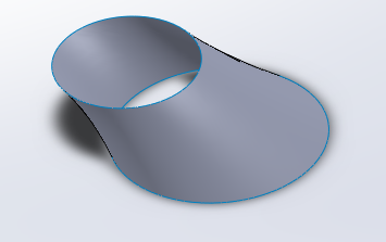

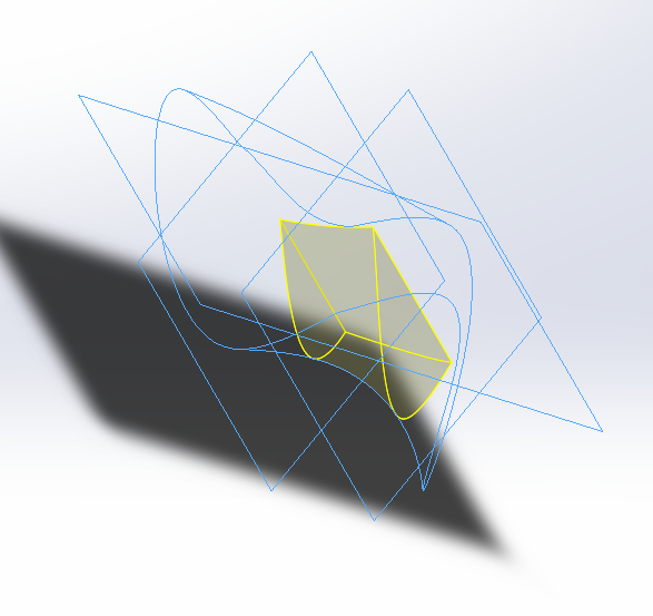
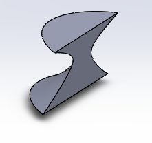
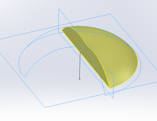
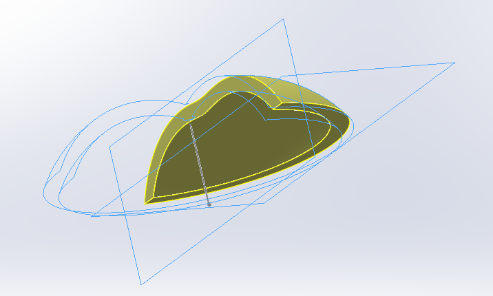
Coon's Surfaces, named for mathematician Steven Coons, are curve-bounded surfaces created by filling in an area between multiple curves. Coon's Surfaces are especially useful in patching surface geometry errors such as those created by inaccurate plane creation resulting in holes in the design. This helps with producing high-fidelity surfaces. These must be created manually in most CAD programs; however, some newer animation software may accomplish creation automatically. This Coon's Patch was created by filling the space between four splines.
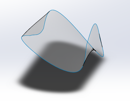
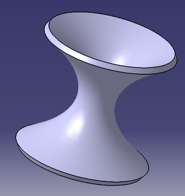
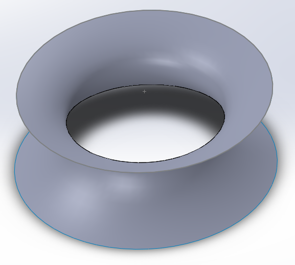
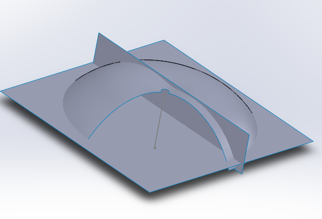
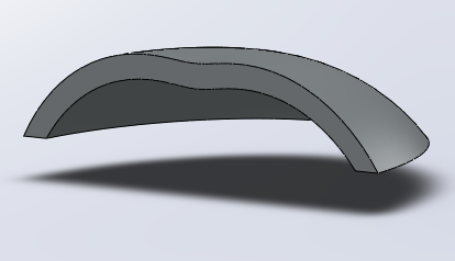
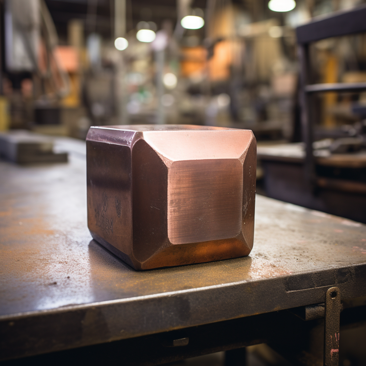
Ruled surfaces are a surface that is defined by boundary curves. It is linearly interpolated to achieve a filled result from lines drawn from the boundary curves. Conic or hyperbolic sections are examples of ruled surfaces. This Ruled Surface was created using offset planes with circular sketches joined with surfaces.
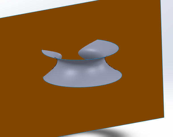
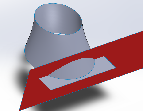
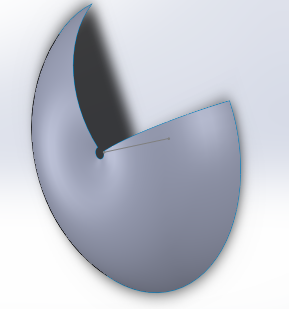
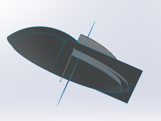
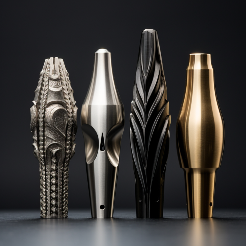
Revolved surfaces are planes, or sketches revolved about an axis by a certain angular displacement. The surface is interpolated between the starting and ending point to create a filled result. These may be created automatically in most CAD programs. This Solid of Revolution was created by revolving a surface sketch.
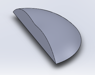
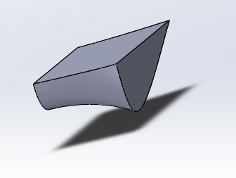
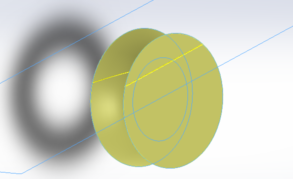
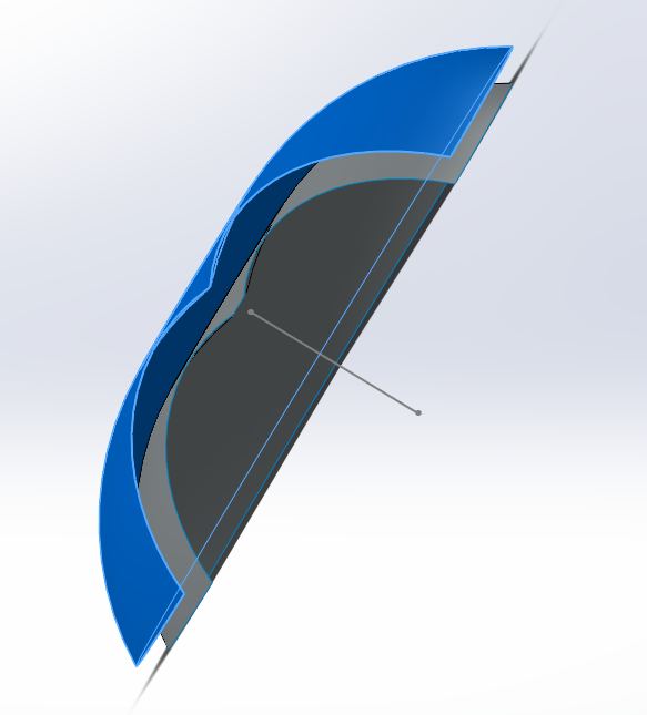
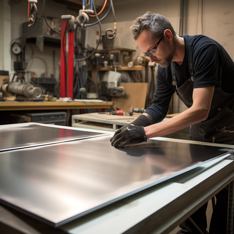
Offset surfaces allow for the creation of a duplicate surface that has the same relative dimensions; however, the dimensions are of a larger magnitude. Offset surfaces are especially useful for creating shell-like surface geometry. The Offset Surface was created by offsetting a previously created surface-based sketch.


Member discussion