Overview of Nuclear Reactor Core Fundamentals
Many factors play into the design of a modern reactor core. One of the first questions that come to mind is uranium fuel's enrichment percentage. A higher enrichment will allow for the use of light water as a moderator, which is more easily replenished; however, a lower enrichment will be less expensive while also requiring a heavy water moderator to compensate for the lower yield of uranium.
Ultimately, a cost versus design analysis will determine the core type. Another question that will come up is fuel loading. How is the fuel to be loaded into the core? Higher and lower-yield uranium can be mixed in a reactor core to produce the desired neutron flux distribution. Localized power peaking is never preferred as it allows for a likely chance to exceed core thermal limits and damage the fuel.
Many factors play into the design of a modern reactor core. One of the first questions that come to mind is uranium fuel's enrichment percentage. A higher enrichment will allow for the use of light water as a moderator, which is more easily replenished; however, a lower enrichment will be less expensive while also requiring a heavy water moderator to compensate for the lower yield of uranium.
Another primary concern concerning reactor core design is poison loading. Fission poisons may be loaded into the core to exert greater control over the flux profile, typically early in core life. Burnable poisons are expected to be used earlier in core life to compensate for a higher fuel loading to allow a longer overall core life. Lumped poisons are those that exert a self-shielding effect. They will exhibit one absorption tendency early on, and due to the thickness and density of the poison, the inner portion of the poison will not be affected by the neutron flux.
As more transmutation of the lumped poison occurs, the inner segment is exposed, resulting in a shift in the neutron flux profile at a designed time. Also of account are fission product poisons such as Samarium and Xenon. Xenon occurs primarily from the decay of Iodine. Samarium is produced from the decay of Neodymium. Both have high neutron absorption cross-sections. Both are removed through burnout from fission. The operator must account for these poisons as they will build up while the reactor is at power.
Typical reactor control is exerted by control rods. Control rods, typically made of silver, hafnium, or cadmium, are materials with a high cross-section of neutron absorption, which act as movable poisons inside the nuclear reaction. By causing localized neutron flux absorption, the overall neutron flux profile of the reactor core can be shaped. Another primary function of control rods is to provide a short-term variation in overall reactor power levels. Changing the control rod location will cause a change in neutron flux levels. As the steam demand on the reactor will remain constant, there will be less heat produced than that being used. Temperatures will lower as a result.
Reactor power will change based on coolant density changing and then return to its standard value. This allows a way to maintain power below a certain threshold for a brief period. The final use of control rods is as a reactor shutdown method. Safety rods are control rods that act quickly enough and with enough negative reactivity to cause the reactor flux levels to lower to an amount that no longer adds heat to the system. The most common method of this is a reactor SCRAM. This is where many control rods are driven to the most negatively reactive position within the core to effect an immediate reactor shutdown. This could be due to a high reactor power density approaching thermal limits, a high reactor startup rate, or an improper flux profile being observed.
There are two types of control rod drive mechanisms. There are electric motor-driven control rods and hydraulic-operated control rods. The primary benefit of electric control rods is greater control over rod speed. Rod speed is essential as the operator must always be able to compensate for a continuous rod withdrawal casualty. Also, rod speed must be high enough to prevent a Xenon-135 precluded startup due to operations at high power before a shutdown. Hydraulically driven control rods are more reliable because an electrical fault will not cause a dropped rod or partial reactor SCRAM. Hydraulically operated control rods also allow for more precise control over rod position. In a pressurized water reactor, rods are generally on the bottom of the core and are withdrawn. In a boiling water reactor, rods are held at the top of the core and pulled out from the bottom.
Other methods of establishing reactor control include loading steam through dump valves to raise reactor power or artificially cool down the reactor plant. Boiling water reactors control power levels primarily by changing the circulation ratio inside the coolant stream by adjusting recirculation rates. This varies the nucleate boiling within the fuel channels, which will change the reactivity inserted due to the voiding of the coolant.
As the moderator is displaced by steam, fewer neutron thermalizations occur, and reactor power will be lower. The primary method that pressurized water reactors have of controlling overall reactor power levels is through what is called a chemical shim. Soluble boron is injected into the coolant, causing a higher cross-section of neutron absorption. As a result, the number of neutrons absorbed in the fuel will be lower, leading to fewer fission events. The soluble boron can be filtered out through a coolant purification system. Chemical shims are desirable because they will not lead to significant variances in local neutron flux levels. The only major disadvantage is the actual use of boron inventory which is readily replenishable.
There are many factors in the physical construction of a reactor vessel. Extreme pressure and temperature conditions over a long period must be accounted for, and constant high neutron embrittlement must also be calculated. Due to the cyclical stresses placed on a reactor vessel, many pressure and temperature limits must be observed throughout the operation of core life. Not only that but there are hydraulic concerns as well. Crud buildup will occur on fuel surfaces, deleting the reactor's thermal performance and leading to local temperature spikes. As a result, careful consideration must be made for the primary coolant loop's equipment arrangement and vessel shape.
Steam generators are used in pressurized water reactors to convert the heat of the primary coolant loop into steam in the secondary loop. Typical construction is based on a U-tube bundle that discharges the reactor's hot coolant loop through a divider plate assembly. Coolant is circulated through the U-tubes back through recirculation pumps. The u-tubes are covered with feed water supplied through a feed ring assembly to prevent uneven cooling. The feed water is boiled and will rise through a series of moisture separators and out an outlet nozzle into the steam system. Moisture separators are necessary due to the extreme risk of moisture impingement damage on delicate turbine blades that rotate at a high rate of speed.
Steam generators are not used in the boiling water reactor design. This causes the BWRs to be more efficient as there is less heat waste in the system. However, the extra separation between the reactor coolant and the steam system will allow pressurized water reactors to operate with lower ambient radiation levels. Also, a pressurized water reactor will have fewer concentration points for radioactive hot spots. Ideally, there should be zero radioactive contamination present in the secondary loop of a pressurized water reactor.
Nuclear safeguards are a vital part of safe plant operations. In the event of a loss of coolant accident, the displacement of the coolant, either through steam bubble formation due to saturation conditions existing or through the physical loss of the coolant through a rupture, will cause local fuel temperatures to rise. As a result, blistering may occur due to the expansion of fission product gasses. These blisters may rupture and cause a release of radionuclides into the coolant stream. These radionuclides will be released outside the reactor vessel if a rupture is present.
Without a containment structure, radionuclides will be released into the environment. Containment structures take on many different types and designs. Also, these structures must have some form of ventilation due to cooling requirements. This further complicates the engineers' job of designing a system capable of withstanding a reactor accident while maintaining ambient temperatures below a design basis. Containment is enforced through hardened bulkhead penetrations, t-seals around valves, and pressure switch-operated ventilation ducting.
On-site emergency diesel generators typically supply emergency power. These generators are usually started by air through fail-open solenoid valves and will automatically align power to the necessary busses to ensure adequate core cooling. It is also power for redundant power to be supplied through manual bus transfer devices located at off-site substations to provide commercial power from another provider.
Two significant forms of emergency cooling are used: safety injection and coolant injection. While they sound similar, their functions are very different. Safety injection is used for a chemical shutdown of the reactor. This may be required for several reasons. It is possible that a loss of coolant accident has led to a partial core meltdown, and poison pins have been melted. If normal coolant injection water were used, it could cause an accidental recriticality accident due to the rewetting of the fuel with dense water.
Coolant injection adds makeup water to the reactor to prevent the fuel plate from uncovering. Also, it can be used as an emergency pressure control method in the event of a loss of pressure control. One possible way of emergency pressure control using an injection system would be to charge the vessel until a pressure relief valve lifts. As long as the injection rate doesn't exceed the speed of coolant lost through the reliefs, the operator can maintain pressure within design tolerances based on relief valve set points.
Seen here is a Boiling Water Reactor schematic. Note that there is no separation between the steam loop and the primary loop other than moisture separators at the top of the reactor vessel.
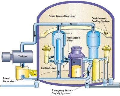
Seen here is a pressurized water reactor drawing. Note that there are three separate loops: a primary coolant loop, a steam loop, and a condensing loop.


Member discussion