Design for Manufacturing: Sheet Metal Bending
The field of Design for Manufacturing provides a lot of excellent tips on how to drive down tooling costs in manufacturing. Today we will review a few tips for working with sheet metal bending.
Bend stages and bend direction typically play an important part in determining tooling for a particular part.
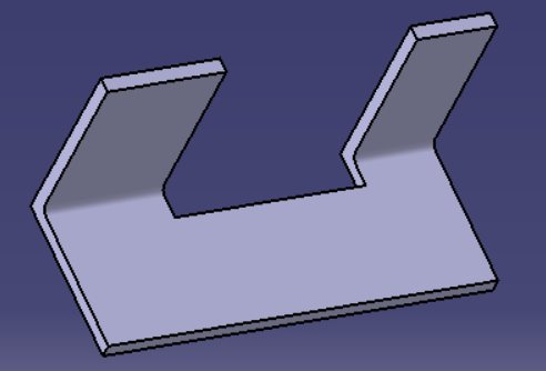
Careful consideration must be made of all parts being designed. In particular, attention should be paid to part geometry and how bending operations will impact that. As each bending operation typically requires its own station, bending operations should be combined whenever possible. This requires part geometry that supports bending along the same axis at the same location.
Part geometry can be laid out to minimize bending. For example, a U-shaped part that must be bent along a single axis may be bent in one operation. In contrast, a Z-shaped part to be bent along the same axis would be much more complicated to bend in a single operation. The same Z-shaped part would require two bending operations to bend each end in different directions. Similarly, that same U-shaped part could not be bent in two different directions in the same operation without particularly complex tooling.
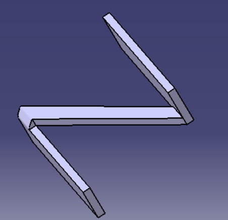
Key points:
(a) Maintain the number of bends to a minimum
(b) Minimize the number of bend directions
(c) If possible, design part geometry to minimize bend operations by combining bending stations.
By following the above key points, you can better provide general guidance to drive tooling costs down for parts production by minimizing bending operations in your machine shop.


Member discussion