CAD Tutorial: Let's Make a Spur Gear!

I was recently asked to show the steps in using a CAD program to make a simple spur gear. Spur gears are the simplest of gears available. Spur gears are simple radially projected gear teeth that provide none of the benefits of more complicated systems.
Please note that this design was just a quick sketch to demonstrate the technique rather than an in-depth design to ensure ideal meshing and tooth strength.
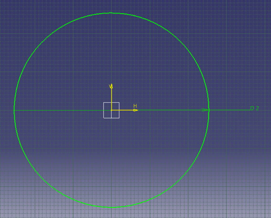
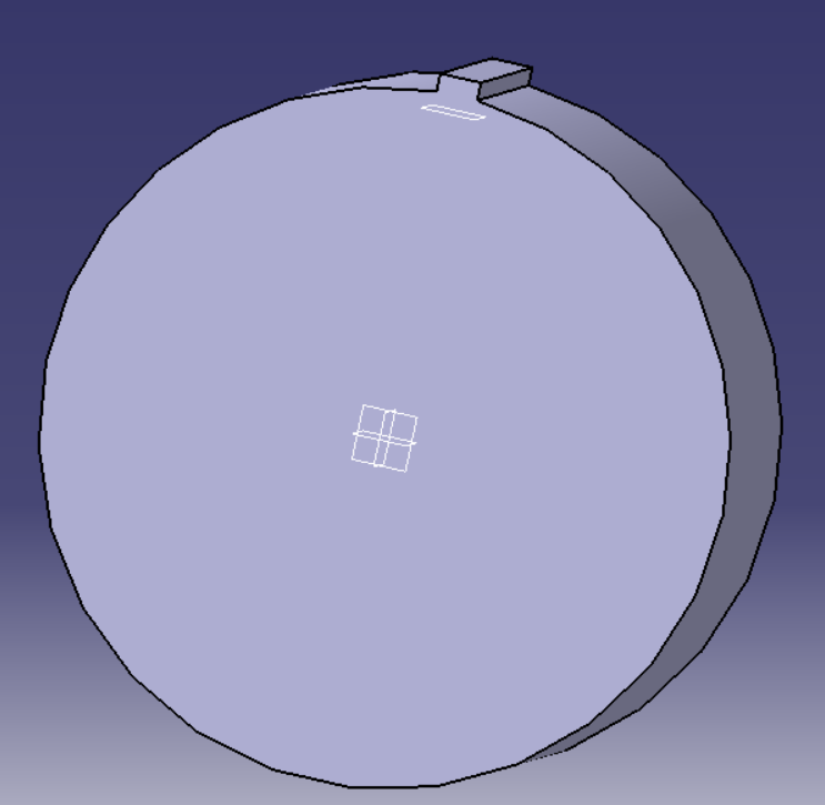
First I make a Sketch of the general shape I want.
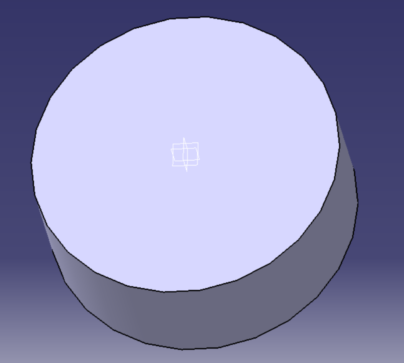
Next, I pad/extrude it out to create a disk.
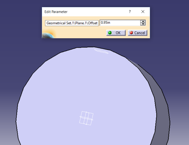
After that, I define a plane that my tooth is going to sit on.
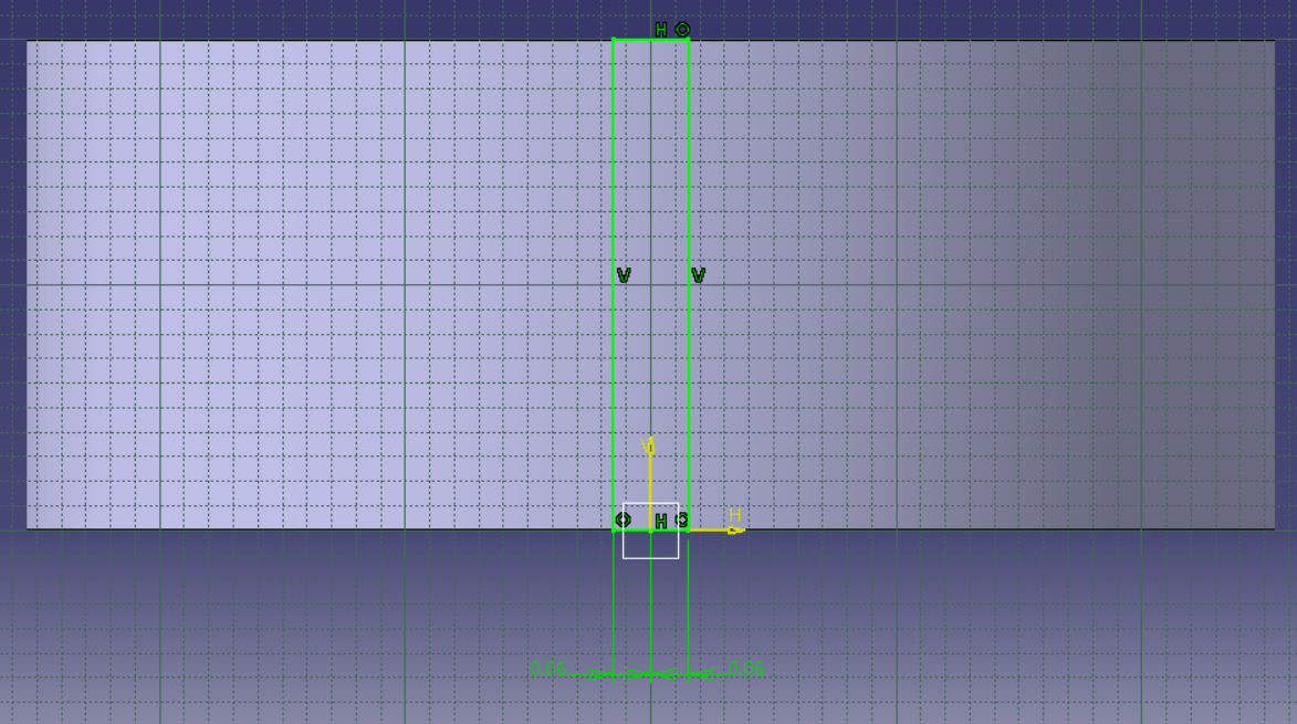
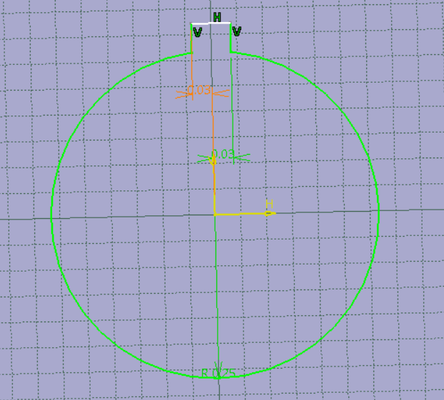
Next, I create my actual gear tooth.
Now I extrude my sketch
That's pretty good, but I'd like to have it chamfered a little so it has a smoother meshing action.
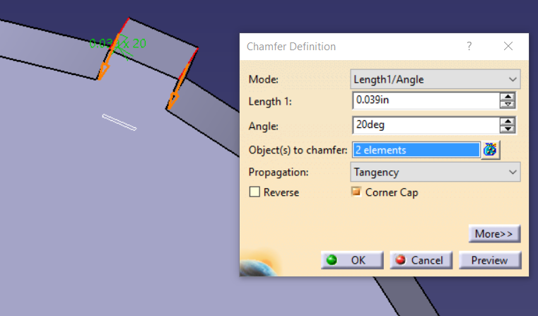
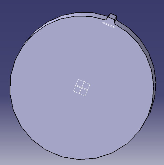
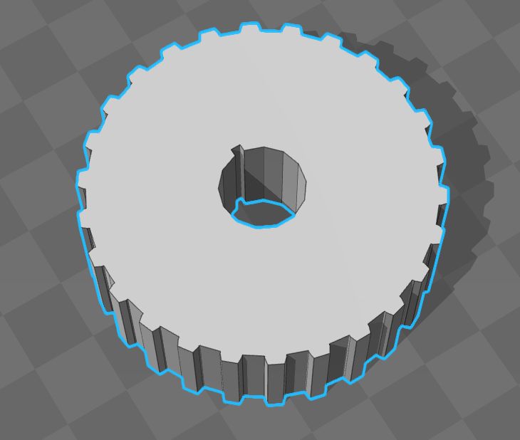
Let's check the result:
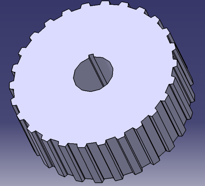
Next I will save myself a lot of time and pattern this tooth to create my gear.
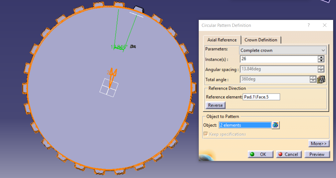
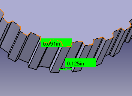
We should verify our meshing action using math which isn't covered in this article. We can do a quick check to make sure the spacing is sufficient, at least.
Now it's time to sketch out my keyway and shaft slot.
One pocket lies between us and completion...
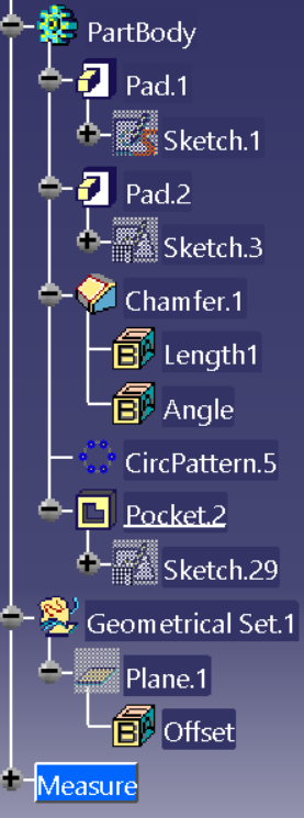
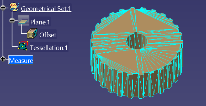
Here's all of the steps from start to finish in my part tree.
Depending on your CAD program, you might have to create a tessellated mesh for your STL export. This allows the file to be saved in a format that relies strictly on a standard listing of coordinates for triangular vertices in Standard Triangle Language. This is a universal method of saving meshes for later use.
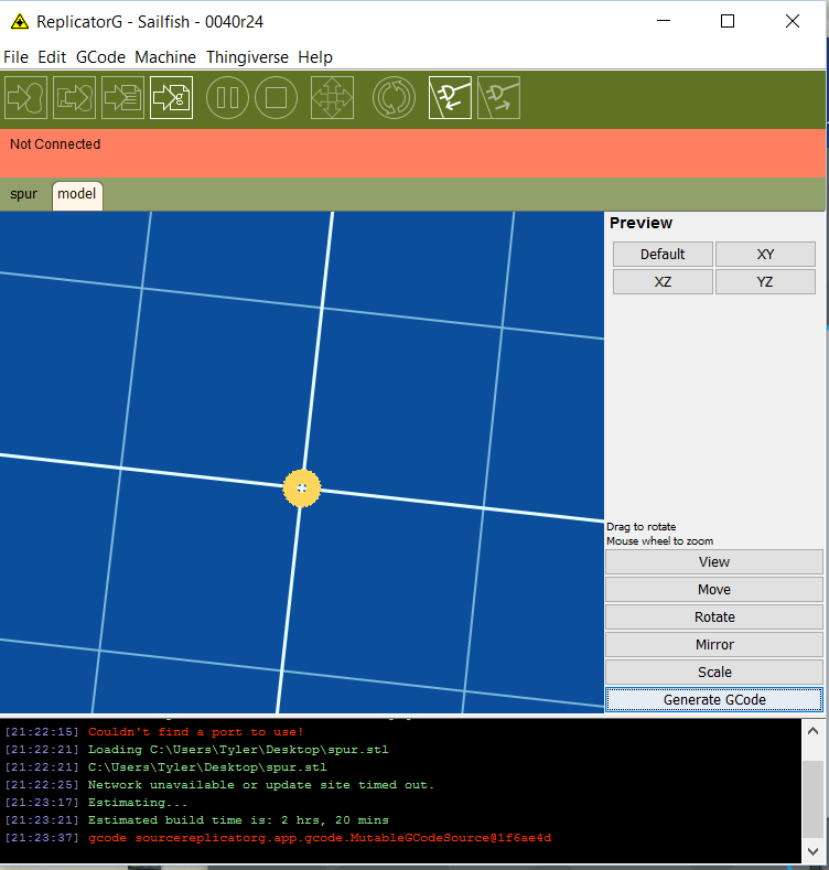
Next, we save our file as an STL and figure out how to get it made. We can either send it to an NC programming system to get a machine toolpath made for machining, or we can send it to a 3d printer.

Member discussion