Basic CAD Terms

Recently someone asked me if I could briefly go over some computer-aided drafting terms.
First of all, I'll briefly discuss feature-based vs. primitive-based modeling.
Primitive-based modeling involves the direct creation of basic shapes which undergo Boolean operations to create models. That means you create two cubes, then subtract one cube from the other to create the desired shape. These "primitive" shapes, such as cubes, spheres, cylinders, etc., are added and subtracted from each other to obtain the desired result. Primitive modeling has generally fallen out of favor over time. A point worth remembering is that some CAD systems that use primitive modeling cannot conduct Boolean operations if only an edge or single point of two models intersect.
Feature-based modeling involves creating sketches that are padded, revolved, pocketed, or otherwise modified three-dimensionally. These three-dimensional manipulations are called "features" of the part. Solidworks uses feature-based geometry exclusively.
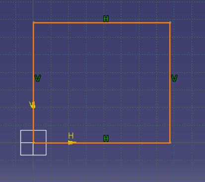
Sketches are the foundational building block of feature-based geometry. Sketches are 2d closed figures (or open in the case of certain surface-based geometry) that can be either extruded (also called padding) or pocketed.
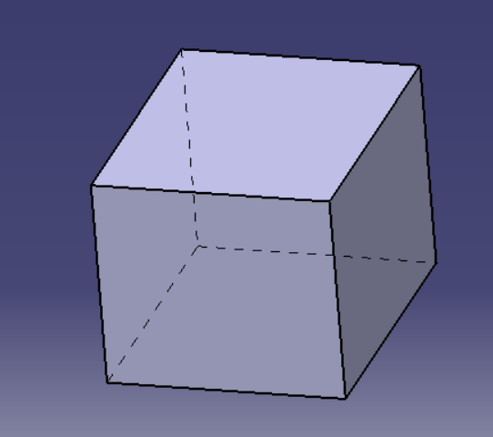
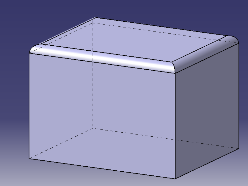
This sketch has been extruded to form a cube. From here, we can assign a sketch to any face. Alternatively, we can modify the edges.
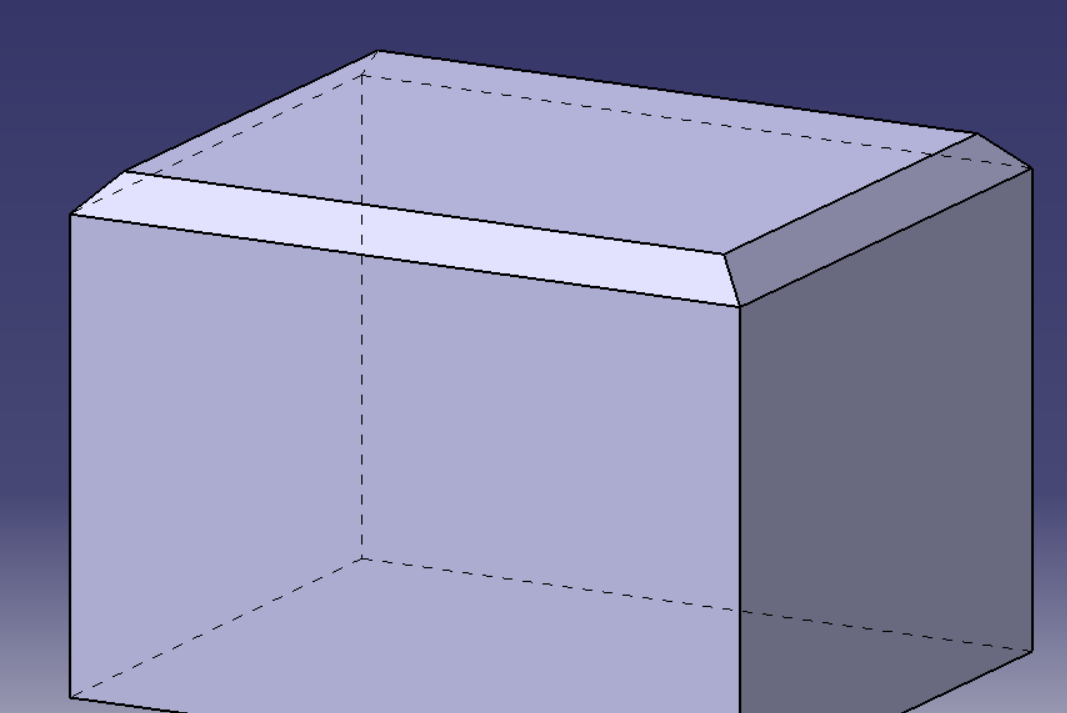
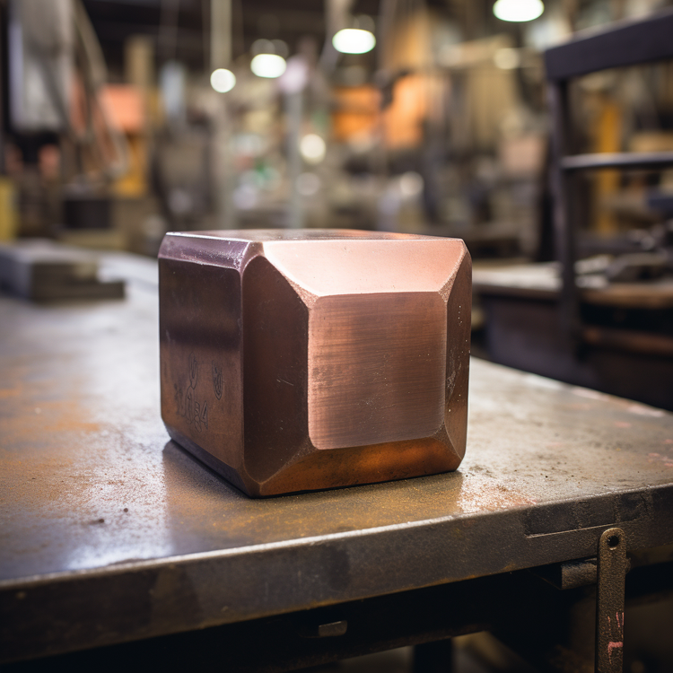
Here we've modified the edges by creating a 45-degree chamfer. We specify both the angle and size of the chamfer to determine our final geometry.
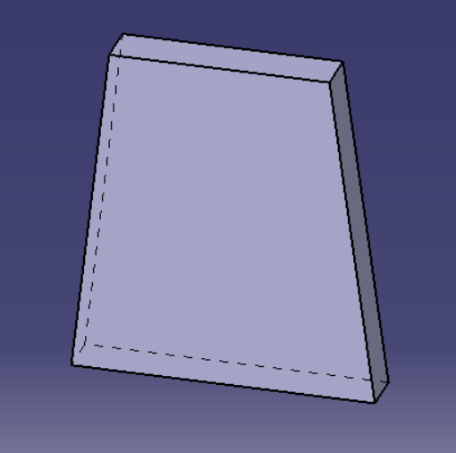
Similarly, we can do the same thing with the face by producing a draft angle. This is useful when working on injection molded parts or parts that have to slide in together.
Filleting is similar to chamfering but produces a radius rather than a sharp angle. This is useful when you don't want sharp edges on a CNC machined part. Everyone likes fillets except for the person that has to produce them.
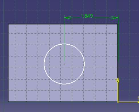
We always want to fully dimensionally constrain our sketches. This means that there are no "free-floating" parts of the sketch. Everything has a set distance (or a formula defining the distance such that we have interlinked assemblies that allow quick redesigns).
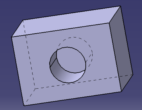
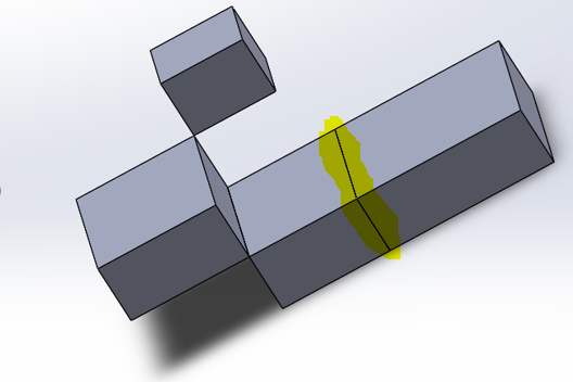
Here we see a pocket used to produce a hole in a box. Always be careful to design features like this with Design for Manufacturing in mind.
The final two terms worth considering are parametric modeling and direct modeling.
Direct modeling is a much less precise method where the general concept of a model is created without regard to dimensions or tolerances. It's very quick and dirty. It also tends to get overly complicated because features are not precisely defined and redesigns cause a large amount of rework.
Parametric modeling involves an exact definition of engineering intent. That means the modeler will use tolerances to ensure adequate fit between parts of an assembly. The modeler will ensure that all parts are completely constrained dimensionally. Parametric modeling will usually use relational design, which allows for the automatic updating of a model. This means that a parametric model of a car may allow for changing the hubcap size to automatically update the wheel size, lug nut size, and wheel well size.
If a quick concept model is required, direct modeling may be the ideal choice. If you have the time to sink into a project, parametric modeling is best.

Member discussion